PDF Download from Google Drive
- What is LCDDRV?
LCDDRV is a general purpose LCD driver board for Sega retro game consoles, Allows RGB
15KHz output to LCD.
Using the 3.5” TFT LCD panel (LQ035NC111), the visibility and response speed are better than the
LCD panel at the time of retro game machines.
Designed for the above purpose.
Input is equipped with composite video / S terminal / RGB (composite sync) for easy use on retro
game machines.
In addition, a high-efficiency switching regulator is used to increase power consumption as much
as possible when incorporating it into a portable game machine. - Before using
This item will require technical fitting and Soldering, we cannot provide support for the fitting of this
part.
Compatible with Sega Mega Drive 1 (MD1) and Mega Drive 2 (MD2). Not compatible with all retro
game consoles. - Attention
About color
Due to the specifications of the chip (secret) used, color bleeding occurs in the horizontal direction
even with RGB input. (So-called YUV422)
○ About vertical sync frequency
It may not appear at horizontal / vertical sync frequencies that are relatively out of NTSC
compliance. In the test of the human pillar, it seems that it was often not reflected on the board with
the vertical synchronization frequency of 60.606… Hz.
○ About video mode
It supports NTSC. (PAL has not been tested because the author does not have an environment)
If the color burst of the composite video or S terminal is a signal that is not NTSC compliant, the
screen may be black and white.
○ About frame delay
There is no framebuffer so there is almost no delay.
○ About aspect ratio
Due to the relationship between the sampling clock and the number of horizontal dots on the liquid
crystal, the width is displayed slightly smaller. It looks like a so-called overscan display.
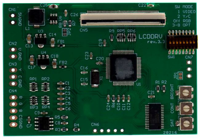
4. LCDDRV board

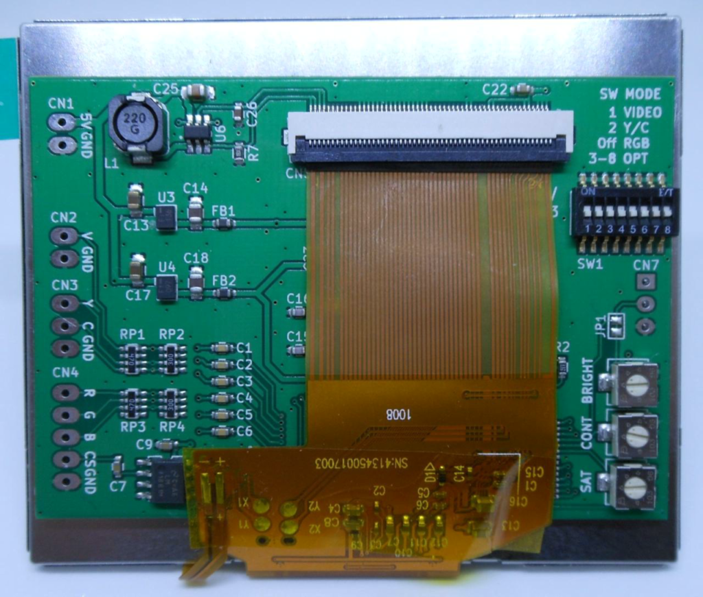
LCDDRV board install example
5. Description of each connector
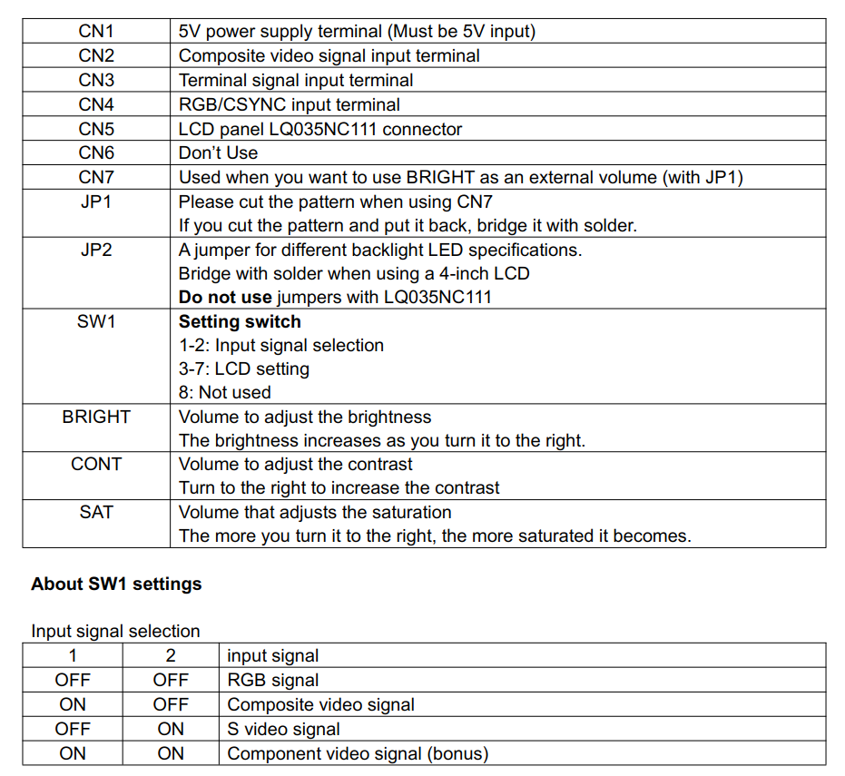
The component signal is a temporary bonus (D1 only).
Input is done from the RGB input terminal of CN5, Y corresponds to G, Pb corresponds to R, and
Pr corresponds to B. Do not use CSYNC for components.
LCD settings
SW1-3 LCD panel inversion mode setting
The liquid crystal uses alternating current to prevent deterioration, but specifies whether it should
be line by line or frame by frame. Depending on the lot of LCD panel and the manufacturer (it
seems that there are some), the flicker of the frame inversion mode seems to be conspicuous, so
the default setting (OFF) is the line inversion mode.
OFF is the line inversion mode, which inverts line by line. ON is the frame inversion mode, which
inverts every frame.
SW1-4 / 5 LCD panel inversion level setting
Depending on the LCD panel, flicker may be noticeable in the frame inversion mode. Since it
differs for each LCD panel, set ON / OFF and use the one with the best result.
If the panel does not fit the flicker no matter which setting you set, set the inversion mode to line
inversion mode. It is recommended to use the one with good display result even in the line
inversion mode.
SW1-6 / 7 Video inversion setting
Left / right inversion and up / down inversion can be inverted independently. If both are turned on,
the image will be rotated 180 degrees.
SW1-8 4 inch LCD mode
Turn it on when using SAT040HS54D08Y0. Be sure to turn this setting on before turning on the
power.
(Note the bold part. Turn it off for previously distributed TMs)
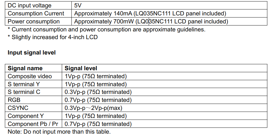
6. Specification
7. About installation
○ Connection to various game consoles
It depends on the RGB output specifications of each game machine.
It’s basically the same as an RGB cable.
○ Video amplifier required / unnecessary
Depending on the specifications of the game console, a video amplifier is not required if you have
a 75Ω driver.
However, if it is necessary to distribute and output, amplify the original signal before entering the
75Ω driver with a video amplifier. (Since there are various specifications from the 75Ω driver to the
output connector, it is easier to put the original signal in the video amplifier.)
○ Composite sync (CSYNC) signal level
The maximum input of the LM1881 (or EL1881) is 2Vp-p, so adjust the CSYNC output level of the
output device before inputting.
○ Connecting the LCD to the LCD connector
The LCD connector uses a flip lock type. Before inserting the FPC board, move the lock part to
open the door. Lock it by closing it after inserting it.
Please note that it is difficult to insert the FPC if the lock part is shallowly opened.
This board is designed to be taped to the back of the LCD. Since through-hole terminals are used
for various signal connection connectors, use thick double-sided tape to prevent short circuits.
Insert the LCD FPC board so that the metal terminal surface is on the bottom of the connector, but
be careful not to insert it at an angle.
Also, be careful not to damage the FPC or connector when inserting the FPC.
○ Wiring to LCDDRV board
Use thick wiring for 5V and GND.
Wire the various signal input terminals as short as possible. Also, connect the GND of various
inputs to the vicinity of the GND of the output destination.
Shielded wires are also effective for video signals.
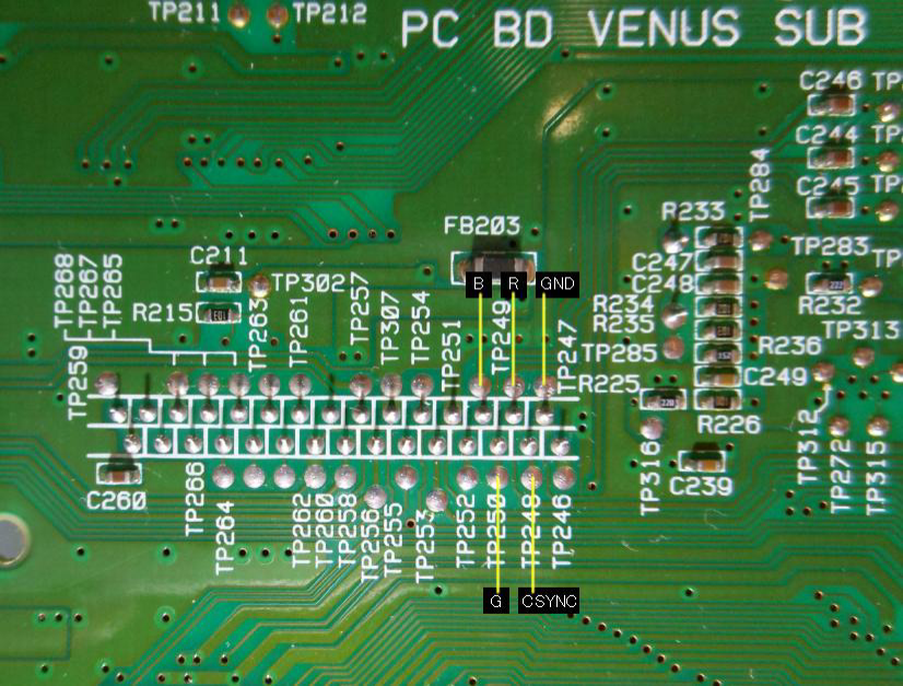
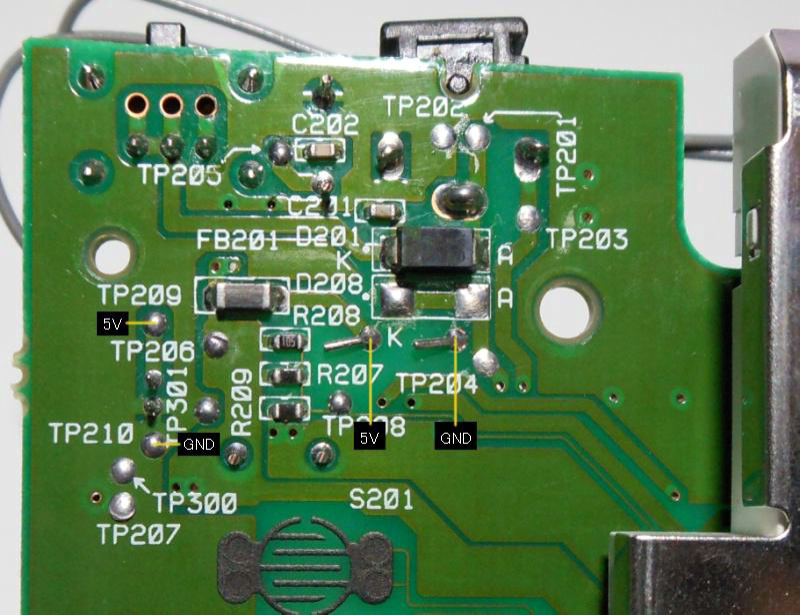
8. SEGA NOMAD RGB connection example
5V power supply for LCDDRV
It is recommended to take 5V from the following points.
The TP209 / TP210 is the original LCD backlight connector, but you may want to reuse the cable.
Please be careful not to make a mistake in plus or minus. (It should be the same as the image
below, but there may be a difference in the board version. Be sure to check the voltage with a
tester)
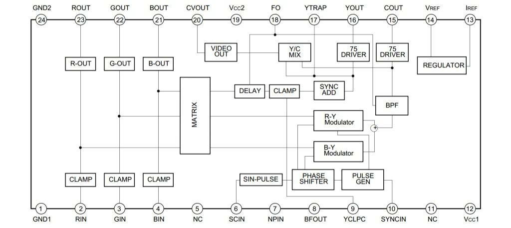
When extracting RGB signals from CXA1645
Input from pins 21 to 23 of the external output pin of CXA1645 through 75Ω to the RGB terminal. Use a capacitor of about
220μF 6.3V.
CSYNC inputs pin 10 to the CSYNC terminal of the LCDDRV. (It seems that there is no particular problem with direct
connection, but if you are concerned, please input by dividing the resistance and voltage)
Thanks to the 75Ω driver, there seems to be no problem connecting the output for the external monitor at the same time.
CXA1645 Pin layout (quoted from the data sheet)
When extracting the original RGB signal for passing through an amplifier
When connecting through an amplifier without using the CXA1645, it is best to take from the point in the following image.
RGB / CSYNC acquisition source example